How to Make a Balsa Wood Canon DSLR Mockup


(Note–if you like this post and other cool DIY projects, make sure to add me on twitter and grab the DOIT feed)
In 2003, Canon posted a how-to on their website about making a Canon 1D mockup in balsa wood. The post sat on their site without much attention for five years, until October 2008, when it got “viral” and spread around the web on all the major sites.
About nine months later, for as-of-now unknown reasons, Canon’s writeup was removed from their site, including most of the associated image files. But thanks to the Wayback Machine, much of that original post is still salvageable. I’ve transposed as much of the information here to help keep it available.
You’ll have to fill in the blanks on the missing images for each of the steps (there were a lot of pics) but you can get a good idea from the ones that are still around.


BUILDING DIMENSIONS
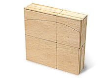
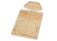
[1] Referring to the drawing, make layer-structure units by gluing together pieces of balsa wood of varying thickness. This will allow the dimensions in the depth direction to be understood in each layer. The lens’ optical axis and film (CCD) surface will be the reference points so draw lines to each position.


[2] Fit the balsa wood to each block. For thicker parts, glue several pieces of balsa wood together.

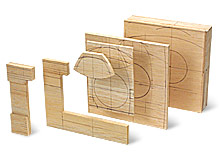
[3] Write in the dimensions for each of the parts and then cut them out. Pictured here are the parts lined up in the order that they will be layered.


TIP: REQUIRED TOOLS
Rulers
Metal ruler, triangular ruler, metric circle template (orange), circumference ruler (green), caliper (front) and hand-made triangle (black)
Gauges
From left: surface gauge, compass
Files & Sanders
From left: sand paper with backing plates (large and small), all types of file rasps and all types of R rasps
Cutters
From left: special tools (chisel with sharp, angled metal saw blades), box cutter (30-degree blade), engraving knife, chisel

CUTTING AND GLUING
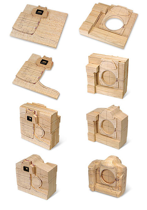
[1] Cut a hole to insert the dummy lens mount.
[2] After cutting out the odd-shaped parts, glue them together.
[3] Glue the back-surface parts together. Assemble the parts that are substantially the same, such as the viewfinder.
[4] Cut out the odd-shaped parts in advance.
[5] This is how it looks when the parts are glued to the back surface.

TIP: FORMING THE HOLE FOR THE MOUNT
[1] Use a drill to open a hole for the jigsaw blade.
[2] Cut a hole with the jigsaw.
[3] Use a sander to remove any distortion, and to make the sides vertical.
![]()

SHAPING
[1] Cut along the outlines.
[2] The back surface.
[3] Shape the curved surface on the side.
[4] Shave out upper portion of the camera’s front surface and a projection on the bottom side of the body.
[5] Shape the surface of the pentaprism portion, the shutter release guard circumference and both shoulders of the upper portion of the camera. Then create the upper portion of the eyecup.
[6] Cut out the grip formation. Shape the shutter pedestal.
[7] Shape around the surface where thumb will rest.
[8] Shape the shutter button.
[9] Create the pentaprism shape. Shape the shutter release guard for vertical shooting.
CREATING THE FINER PORTIONS
[1] Create the LCD window.
[2] Work further on the area around the buttons.
[3] Create a group of buttons on the front surface.
[4] Create a group of buttons on the back surface.

TIP: CREATING THE PARTS
[1] Create a group of buttons. Use a template to draw the shape.
[2] Draw the reference line on the sides.
[3] Draw the positioning lines.
[4] Use a motorized tool to form the cavity of the depression R.
[5] Use a curve ruler to draw a line and to check the amount that you have cut.
[6] Create the parts. Make the rotation dial. Glue a different thickness piece cross-wise to increase strength. Based on the reference lines, use a compass, a template and a ruler to draw a circle.
[7] Carve out the lever.
